Home Automation, simple project. (simple science project)
Home Automation, as simple as possible.
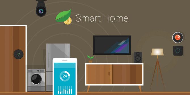
We have come with most easiest way to automate anything that you want with proper changes in instruction given below.
It could be a great science project, in your schools and colleges which will stand you out from others.
- You will need :-
- Laptop
- arduino softeware installed on you pc/laptop.
- circuit -1.Node MCU 2.LM 35 (to read tempreture) 3.relay module
- USB cable
- Blynk app installed on smart phone(to controll from your phone)
- common wi-fi connection on phone and and pc.
- Cost of whole project :- Around 700-800

Instruction :-
1. Board Preferences:- http://arduino.esp8266.com/stable/package_esp8266com_index.json
then go to tools>board>board manager
search for esp8266 and then install
2. Select tools>boards>NodeMCU 0.9
Select port.
if port is not visible then check for drivers
USB Driver and USB to UART Driver
USB Driver:-
https://sparks.gogo.co.nz/ch340.html
USB to UART Driver:-
https://www.silabs.com/products/development-tools/software/usb-to-uart-bridge-vcp-drivers
3. Built-in LED Glow
File>Example>ESP8266>Blink
Compile and upload
Change the values and run again.

4. External LED
Connect the simple circuit and run the code.
5. External LED 2 at once
Connect them in series and run the code.
6. Controlling through web server
Provide them a code and explain them the code.
Then upload and observe the serial monitor.
Check the baud rate if error occurs.
If still error continues then download 8266 NodeMCU Library
NodeMCU Libraries:-
https://github.com/esp8266/Arduino
7. Control through Blynk app.
Download the blynk app from playstore
register with your email account(prefer gmail over facebook)
then click on Create
Give name to project
select board as nodemcu
choose wifi type
click create to finish
then blynk will send a auth code to your emailid registered now.
Copy that code for futher use
Add button to your project
click on button and rename it with whatever you want
select digital pin d3
change the output from 0 - 1 to 1 - 0
and change mode from push to switch
open mail and copy the auth code
download blynk library and install
Blynk Libraries:- https://github.com/blynkkk/blynk-library/release
extract the zip file
copy the files and paste in Arduino folder in the documents folder
now open arduino ide and go to file->examples->blynk->boards_wifi->esp8266_standalone
run the code and change the credentials properly using auth code.
now tap play button to start and power the nodemcu.
8. Google Assistance Blynk and IFTTT Connection
Go to IFTTT
click on create
click on "+ this" and search google assistance
select say a phrase
type in the phrases you wish to say
write the response you wish from google assistance
click on create trigger
then click on "+ that" and search for webhooks
WebHooks is a tool which allow us to send a web request to blynk app
then click on make a web request
copy blynk url:-
Blynk Server (INDIA):-
http://188.166.206.43/authcode/update/D0
*NOTE:- D3 pin of nodemcu corresponds to D0 pin of arduino
select Put
select application/json
write ["0"] to turn on the switch
*{Body =["0"] ( Here 0 means to turn on digital pin D3 for Google Assistance)}
repeat same for turning off with ["1"] and save
then go to arduino IDE and select file>examples>Blynk>Boards_Wifi>ESP8266_Standalone
run that code on nodemcu changing the username,password of wifi and the auth token recieved via email.
Here is a picture of Node MCU (Home Automation) :-

clicke here to buy:- https://amzn.to/2PTqXsi
Here is picture of LM 35 (Home Automation):-
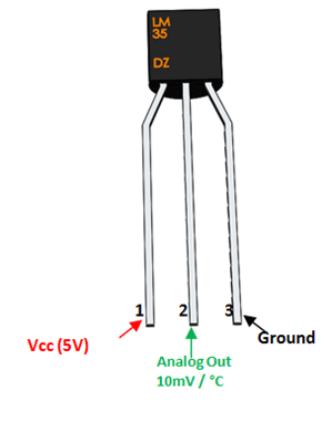
click here to buy:- https://amzn.to/31025Ai
Here is connection setup (Home Automation):-

Have look on budget friendly laptops click here :-
https://reviewstechscience.blogspot.com/2019/05/best-laptop-in-lowest-budget-may-2019_24.html
https://reviewstechscience.blogspot.com/2019/05/best-laptop-in-lowest-budget-may-2019_24.html
- codes :-
Just copy past the bellowed codes in software
- External LED :-
#define LED D1 // Led in NodeMCU at pin GPIO5 (D1).
void setup() {
pinMode(LED, OUTPUT); // set the digital pin as output.
}
void loop() {
digitalWrite(LED, HIGH);// turn the LED on.
delay(2500); // wait for 1 second.
digitalWrite(LED, LOW); // turn the LED off.
delay(500); // wait for 1 second.
}
- External LED 2:-
#define LED1 D1 // Led in NodeMCU at pin GPIO5 (D1).
#define LED2 D2 // Led in NodeMCU at pin GPIO4 (D2).
void setup() {
pinMode(LED1, OUTPUT); // set the digital pin as output.
pinMode(LED2, OUTPUT); // set the digital pin as output.
}
void loop() {
digitalWrite(LED1, HIGH);
digitalWrite(LED2, HIGH);// turn the LED on.
delay(200); // wait for 1 second.
digitalWrite(LED1, LOW); // turn the LED off.
// wait for 1 second.
// turn the LED on.
// wait for 1 second.
digitalWrite(LED2, LOW); // turn the LED off.
delay(200); // wait for 1 second.
}
- LED controll through Web service :-
#include <ESP8266WiFi.h>
// Replace with your network credentials
const char* ssid = "shubham"; -here, put your wifi name
const char* password = "98231600"; -put password here
// Set web server port number to 80
WiFiServer server(80);
// Variable to store the HTTP request
String header;
// Auxiliar variables to store the current output state
String output1State = "off";
String output2State = "off";
// Assign output variables to GPIO pins
const int output1 = D1;
const int output2 = D2;
void setup() {
Serial.begin(115200);
// Initialize the output variables as outputs
pinMode(output1, OUTPUT);
pinMode(output2, OUTPUT);
// Set outputs to LOW
digitalWrite(output1, LOW);
digitalWrite(output2, LOW);
// Connect to Wi-Fi network with SSID and password
Serial.print("Connecting to ");
Serial.println(ssid);
WiFi.begin(ssid, password);
while (WiFi.status() != WL_CONNECTED) {
delay(500);
Serial.print(".");
}
// Print local IP address and start web server
Serial.println("");
Serial.println("WiFi connected.");
Serial.println("IP address: ");
Serial.println(WiFi.localIP());
server.begin();
}
void loop(){
WiFiClient client = server.available(); // Listen for incoming clients
if (client) { // If a new client connects,
Serial.println("New Client."); // print a message out in the serial port
String currentLine = ""; // make a String to hold incoming data from the client
while (client.connected()) { // loop while the client's connected
if (client.available()) { // if there's bytes to read from the client,
char c = client.read(); // read a byte, then
Serial.write(c); // print it out the serial monitor
header += c;
if (c == '\n') { // if the byte is a newline character
// if the current line is blank, you got two newline characters in a row.
// that's the end of the client HTTP request, so send a response:
if (currentLine.length() == 0) {
// HTTP headers always start with a response code (e.g. HTTP/1.1 200 OK)
// and a content-type so the client knows what's coming, then a blank line:
client.println("HTTP/1.1 200 OK");
client.println("Content-type:text/html");
client.println("Connection: close");
client.println();
// turns the GPIOs on and off
if (header.indexOf("GET /1/on") >= 0) {
Serial.println("Red LED on");
output1State = "on";
digitalWrite(output1, HIGH);
} else if (header.indexOf("GET /1/off") >= 0) {
Serial.println("RED LED off");
output1State = "off";
digitalWrite(output1, LOW);
} else if (header.indexOf("GET /2/on") >= 0) {
Serial.println("Green LED on");
output2State = "on";
digitalWrite(output2, HIGH);
} else if (header.indexOf("GET /2/off") >= 0) {
Serial.println("Green LED off");
output2State = "off";
digitalWrite(output2, LOW);
}
// Display the HTML web page
client.println("<!DOCTYPE html><html>");
client.println("<head><meta name=\"viewport\" content=\"width=device-width, initial-scale=1\">");
client.println("<link rel=\"icon\" href=\"data:,\">");
// CSS to style the on/off buttons
// Feel free to change the background-color and font-size attributes to fit your preferences
client.println("<style>html { font-family: Helvetica; display: inline-block; margin: 0px auto; text-align: center;}");
client.println(".button { background-color: #BDB76B; border: none; color: white; padding: 16px 40px;");
client.println("text-decoration: none; font-size: 30px; margin: 2px; cursor: pointer;}");
client.println(".button2 {background-color: #BDB76B;}</style></head>");
// Web Page Heading
client.println("<body><h1>Contoling LED Through ESP8266 Web Server</h1>");
// Display current state, and ON/OFF buttons for GPIO 5
client.println("<p>Red LED " + output1State + "</p>");
// If the output1State is off, it displays the ON button
if (output1State=="off") {
client.println("<p><a href=\"/1/on\"><button class=\"button\">ON</button></a></p>");
} else {
client.println("<p><a href=\"/1/off\"><button class=\"button button2\">OFF</button></a></p>");
}
// Display current state, and ON/OFF buttons for GPIO 4
client.println("<p>Green LED " + output2State + "</p>");
// If the output2State is off, it displays the ON button
if (output2State=="off") {
client.println("<p><a href=\"/2/on\"><button class=\"button\">ON</button></a></p>");
} else {
client.println("<p><a href=\"/2/off\"><button class=\"button button2\">OFF</button></a></p>");
}
client.println("</body></html>");
// The HTTP response ends with another blank line
client.println();
// Break out of the while loop
break;
} else { // if you got a newline, then clear currentLine
currentLine = "";
}
} else if (c != '\r') { // if you got anything else but a carriage return character,
currentLine += c; // add it to the end of the currentLine
}
}
}
// Clear the header variable
header = "";
// Close the connection
client.stop();
Serial.println("Client disconnected.");
Serial.println("");
}
}

click here to buy :)
https://amzn.to/31fyPpa
Follow every thing correctly,
In case of any queries then let me know it,
please comment below
Thank you.


Good
ReplyDelete